Tesla runs a bug bounty program that invites researchers to find security vulnerabilities in their vehicles. To participate, I needed the actual hardware, so I started looking for Tesla Model 3 parts on eBay. My goal was to get a Tesla car computer and touchscreen running on my desk, booting the car’s operating system.
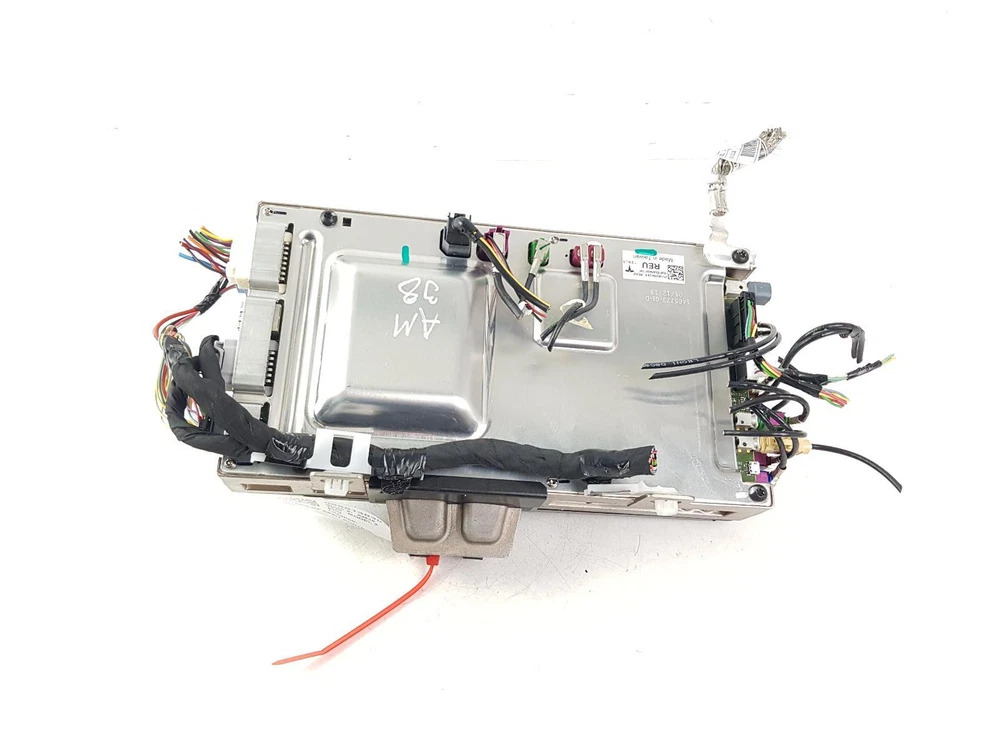
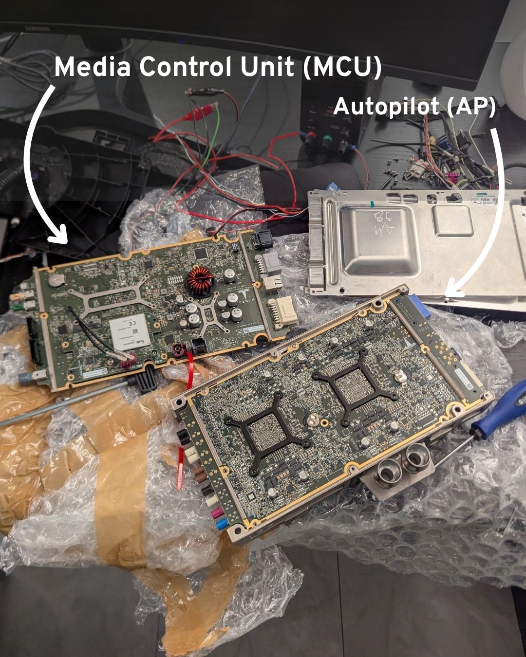
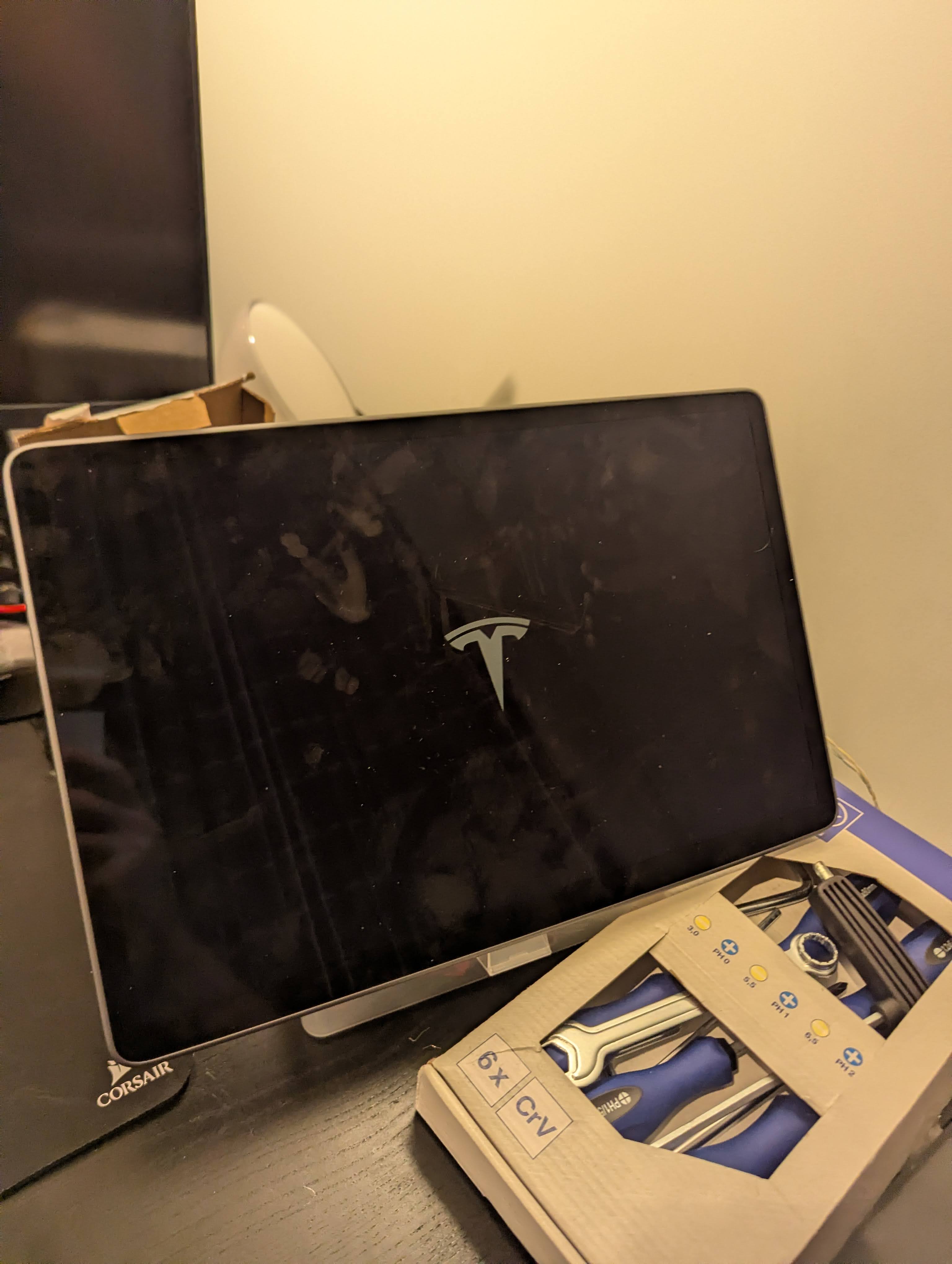
The car computer consists of two parts - the MCU (Media Control Unit) and the autopilot computer (AP) layered on top of each other. In the car, the computer is located in front of the passenger seat, roughly behind the glovebox. The part itself is the size of an iPad and the thickness of a ~500 page book and is covered in a water-cooled metal casing:
By searching for “Tesla Model 3 MCU” on Ebay, I found quite a lot of results in the $200 - $300 USD price range. Looking at the listings, I found that many of these sellers are “salvaging” companies who buy crashed cars, take them apart, and list all parts for sale individually. Sometimes, they even include a photo of the original crashed car and a way to filter their listings for parts extracted from the same vehicle.
To boot the car up and interact with it, I needed a few more things:
- A DC power supply capable of providing 12V
- A touchscreen module from a salvaged Model 3
- The display cable to connect them together
For the power supply, I went with an adjustable 0-30V model from Amazon. There was a 5 ampere and a 10A version available, at the time, I figured it’s safer to have some headroom and went with the 10A version – it was a very good decision, as it later turned out, the full setup could consume up to 8A at peak times. The Model 3 screens were surprisingly expensive on Ebay, I assume that is because it is a popular part to replace. I found a pretty good deal for 175 USD.
The last and most difficult part to order was the cable which connects the MCU to the screen. I needed this because both the computer and a screen were being sold with the cables cut a few centimeters after the connector (interestingly most sellers did that, instead of just unplugging the cables).
This is when I discovered that Tesla publishes the wiring “Electrical Reference” for all of its cars publicly. On their service website, you can look up a specific car model, search for a component (such as the display), and it will show you exactly how the part should be wired up, what cables/connectors are used, and even what the different pins are responsible for inside a single connector:
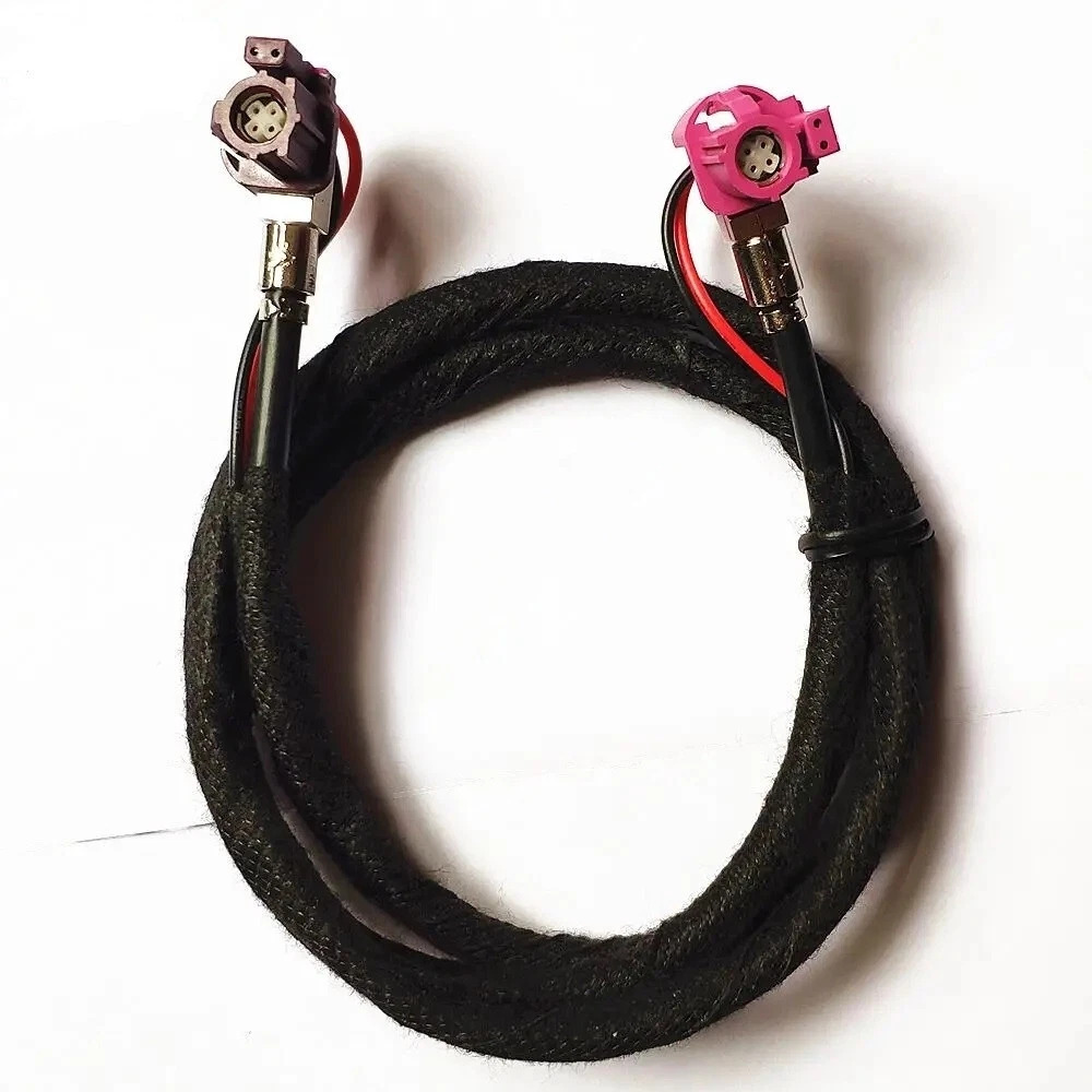
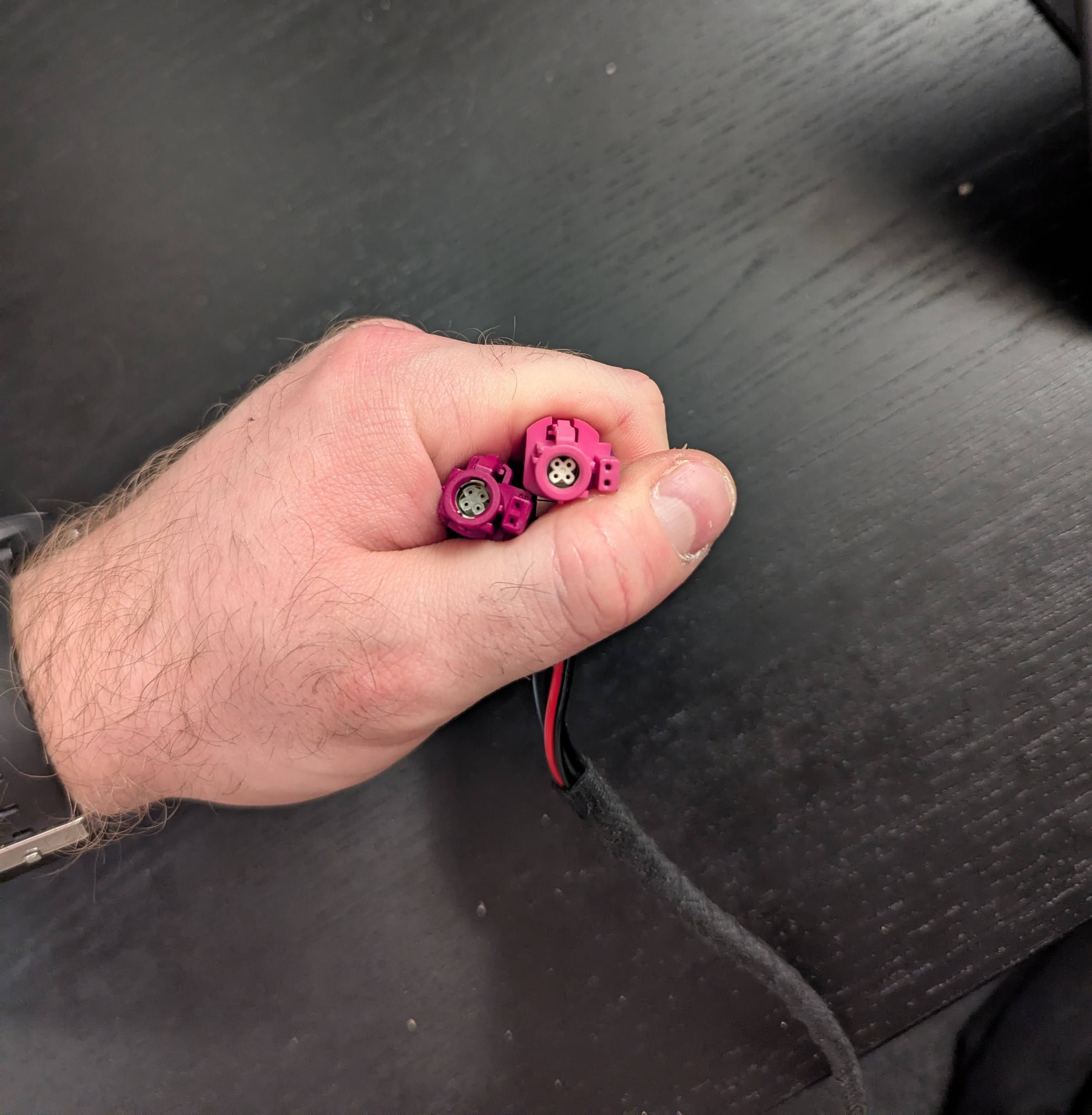
Turns out the display uses a 6-pin cable (2 for 12V and ground, 4 for data) with a special Rosenberger 99K10D-1D5A5-D connector. I soon discovered that unless you are a car manufacturer ordering in bulk, there is no way you are buying a single Rosenberger cable like this. No Ebay listings, nothing on Aliexpress, essentially no search results at all.
After digging around a bit, I found that this cable is very similar to a more widely used automotive cable called “LVDS”, which is used to transfer video in BMW cars. At first sight, the connectors looked like a perfect match to my Rosenberger, so I placed an order:
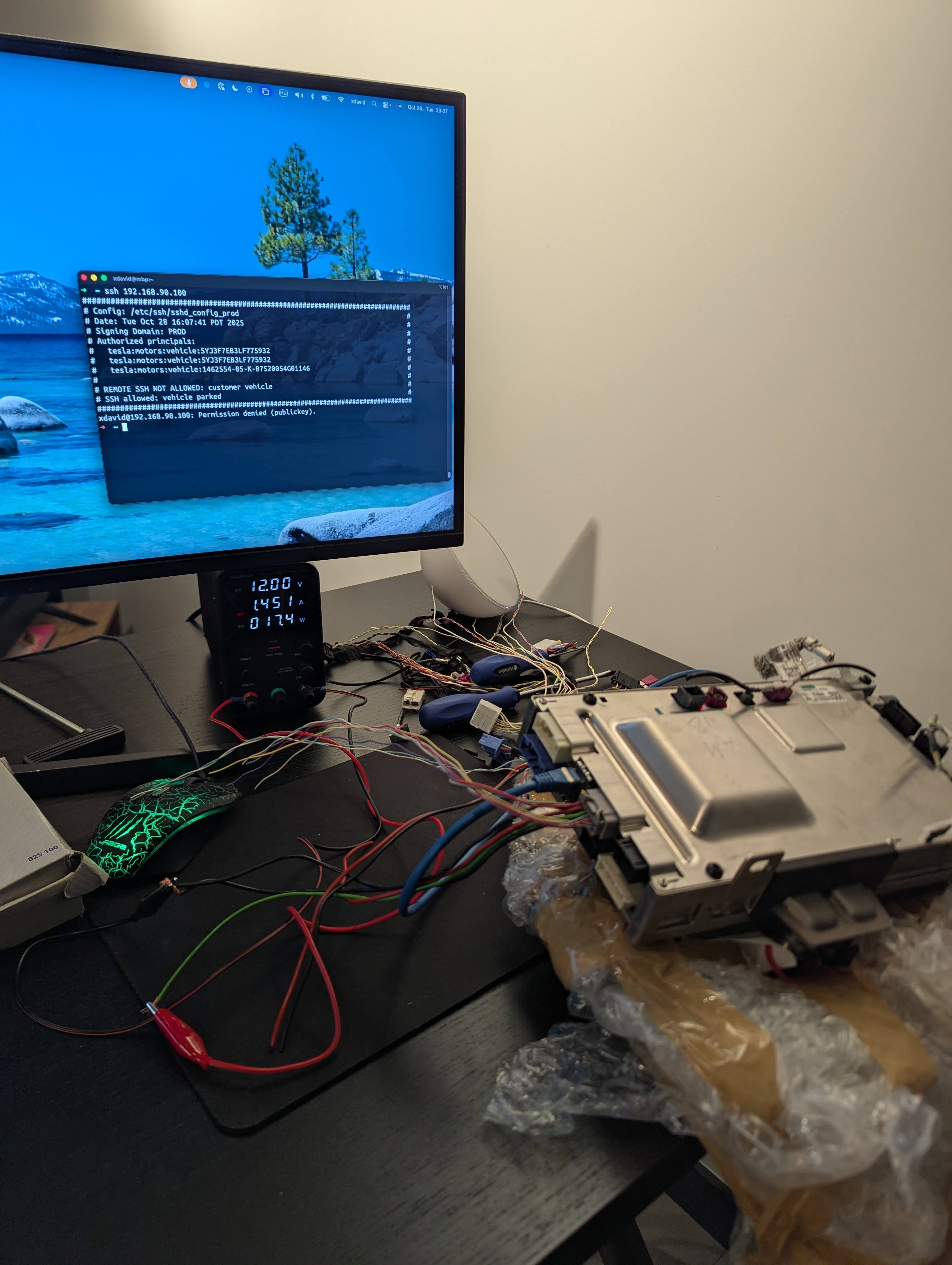
The computer arrived first. To attempt to power it on, I looked up which pin of which connector I needed to attach 12V and ground to using the Tesla schematics & the few pictures online of people doing the same desk-MCU setup. Since the computer included the shortly cut cables, I was able to strip the relevant wires and attach the power supply’s clips to the right ones:
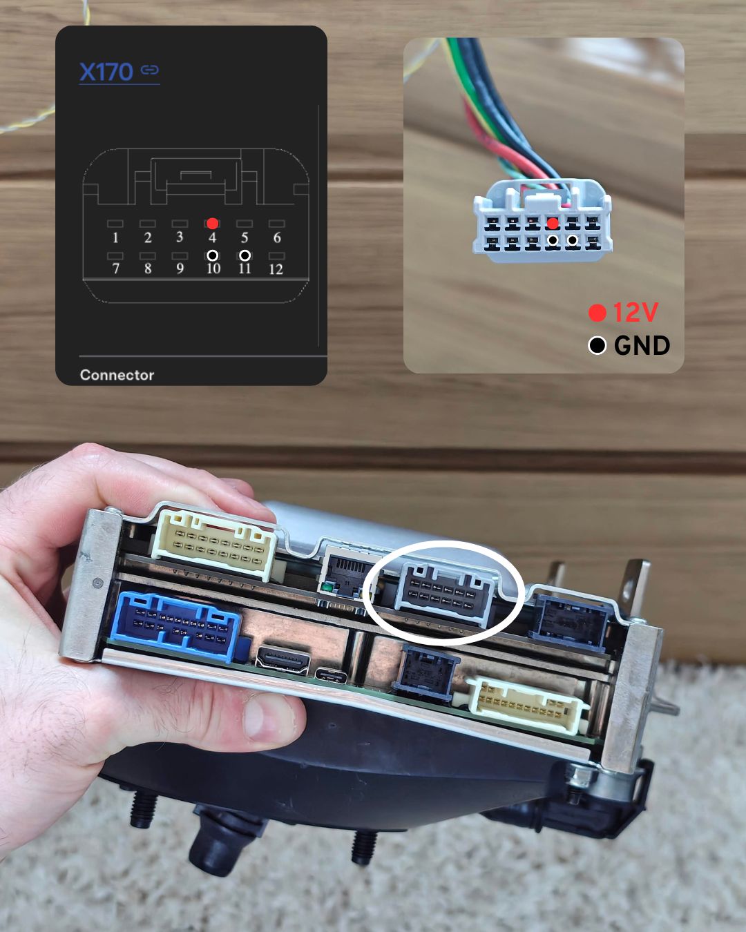
I saw a couple of red LEDs start flashing, and the computer started up! Since I had no screen yet, there were not many ways to interact with the car. Reading @lewurm’s previous research on GitHub I knew that, at least in older car versions, there was a network inside the car, with some components having their own webserver. I connected an Ethernet cable to the port next to the power connector and to my laptop.
This network does not have DHCP, so you have to manually set your IP address. The IP you select has to be 192.168.90.X/24, and should be higher than 192.168.90.105 to not conflict with other hosts on the network. On Reddit, I found the contents of an older /etc/hosts file from a car which shows the hosts that are normally associated with specific IPs:
192.168.90.100 cid ice # mcu
192.168.90.100 ic # only in Model X/S | IC = instrument cluster
192.168.90.102 gw # gateway
192.168.90.103 ap ape # ap = autopilot
192.168.90.104 lb # no clue
192.168.90.105 ap-b ape-b # also autopilot
192.168.90.30 tuner # Also no clue
192.168.90.60 modem # this has the ftp server
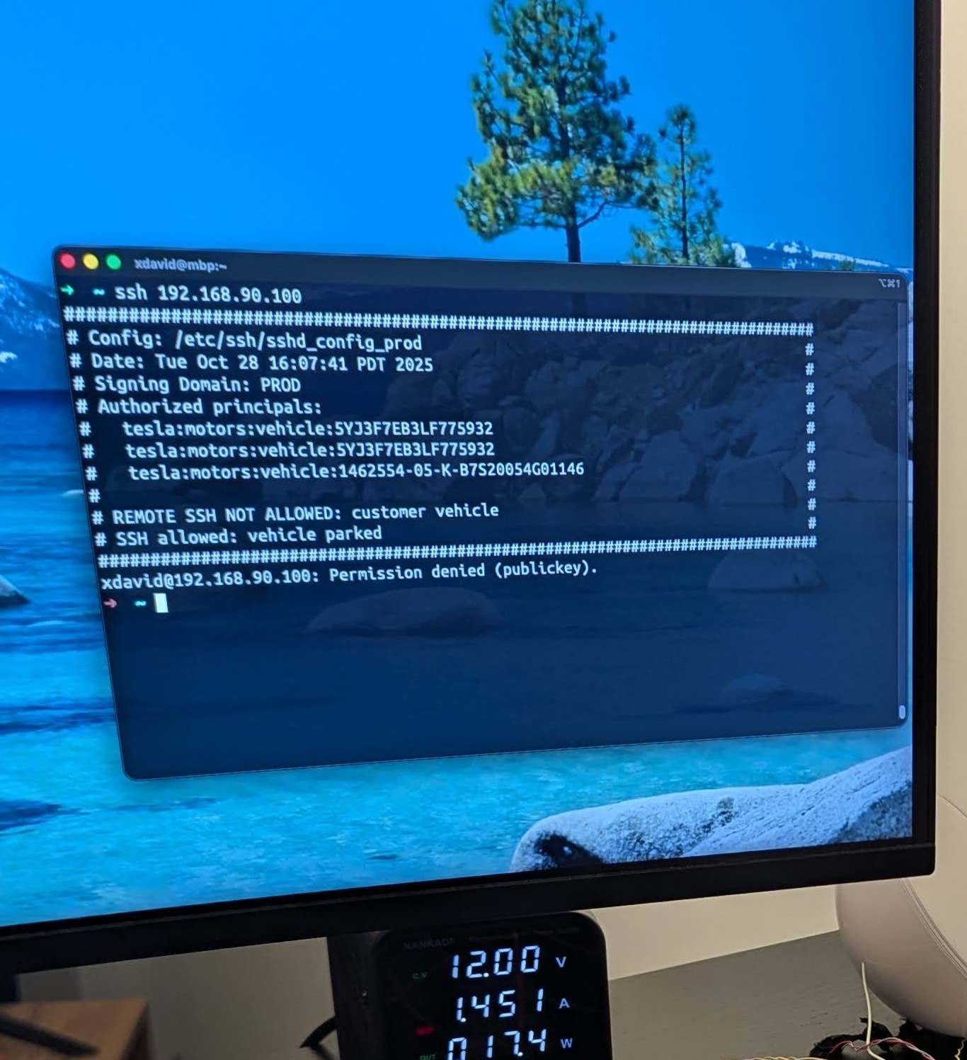
@lewurm’s blog mentioned that SSH on port :22 and a webserver on :8080 was open on 192.168.90.100, the MCU. Was this still the case on newer models? Yes!
I had already found 2 services to explore on the MCU:
- An SSH server which states “SSH allowed: vehicle parked” - quite funny given the circumstances
- This SSH server requires specially signed SSH keys which only Tesla is supposed to be able to generate.
- Interestingly, Tesla offers a “Root access program” on their bug bounty program. Researchers who find at least one valid “rooting” vulnerability will receive a permanent SSH certificate for their own car, allowing them to log in as root and continue their research further. – A nice perk, as it is much easier to find additional vulnerabilities once you are on the inside.
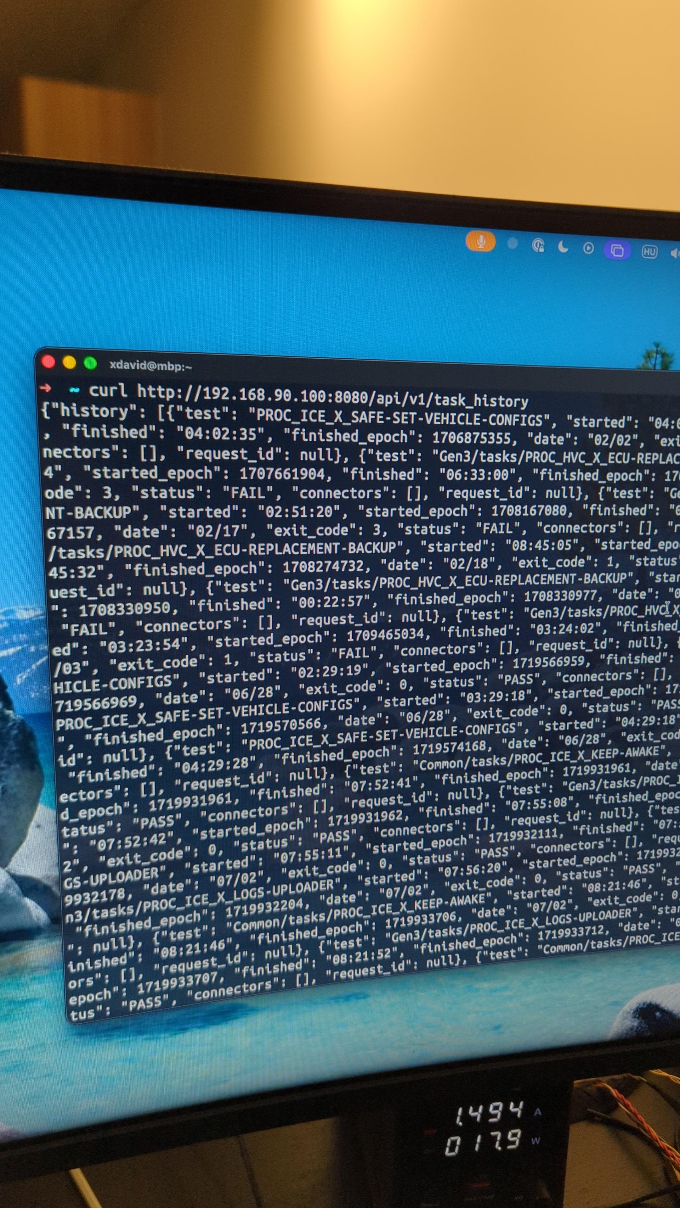
- A REST-like API on
:8080which returned a history of “tasks”- This service is called “ODIN” (On-Board Diagnostic Interface Network), and is intentionally exposed to be used by Tesla’s diagnostics tool “Toolbox”.
Around this time, I also removed the metal shielding to see exactly what the boards look like inside. You can see the two different boards which were stacked on top of each other:
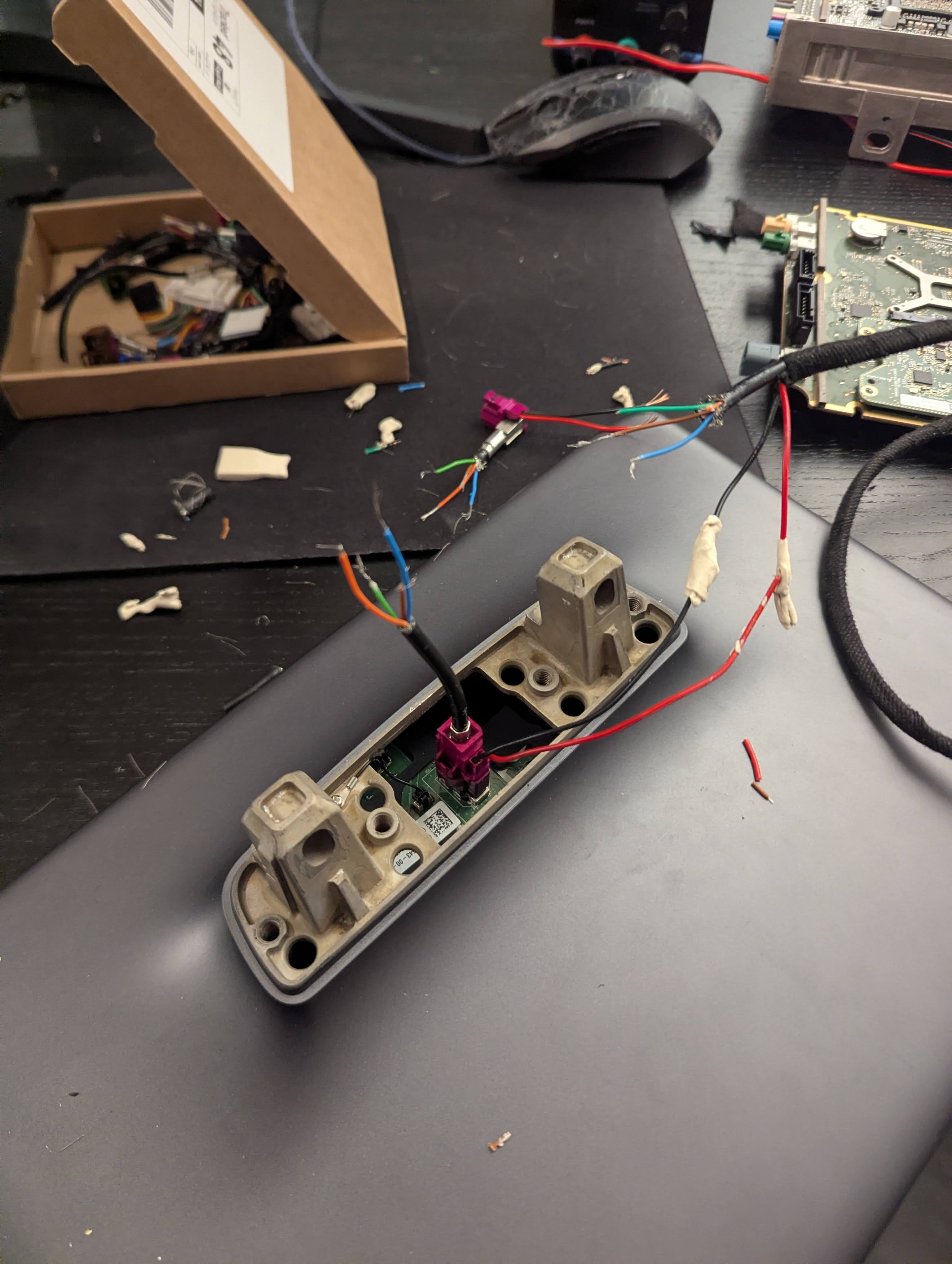
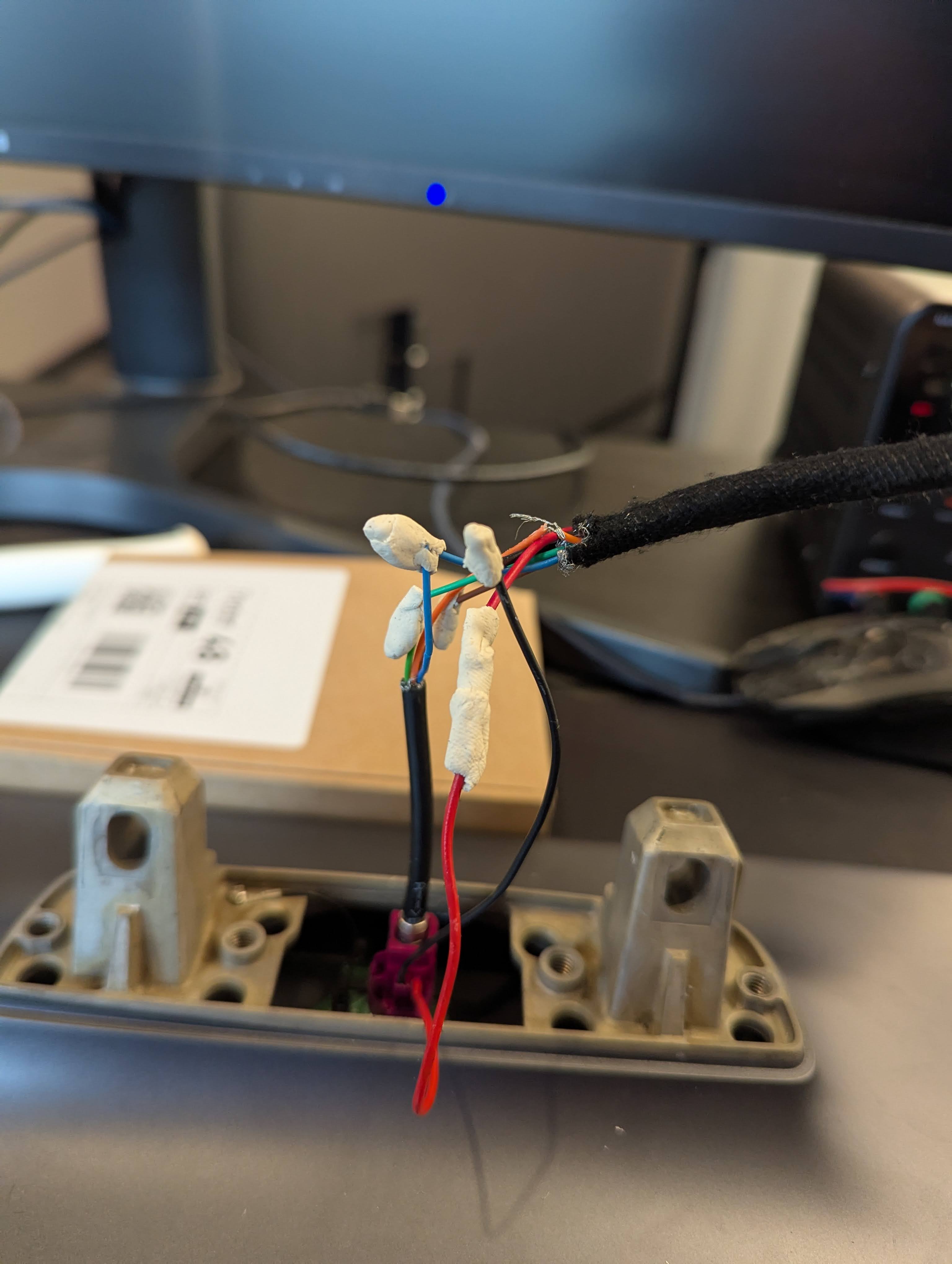
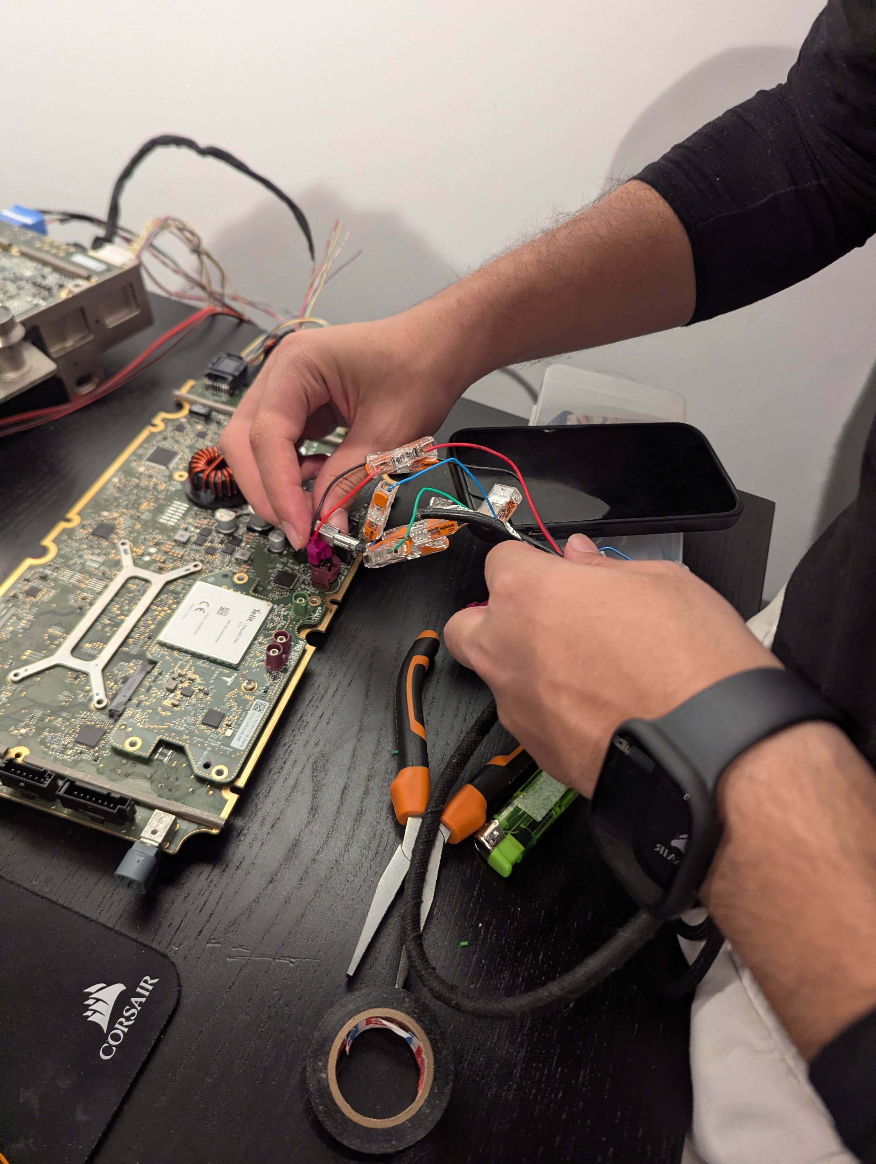
Once the screen and the BMW LVDS cable arrived, it unfortunately became clear that the connector is not going to fit. The BMW connector was much thicker on the sides and it was not possible to plug it into the screen. This led to some super sketchy improvised attempts to strip the two original “tail” cables from the MCU and the screen and connect the individual wires together. The wires were really sensitive and thin. The setup worked for a couple of seconds, but caused wire debris to fall on the PCB and short it, burning one of the power controller chips:
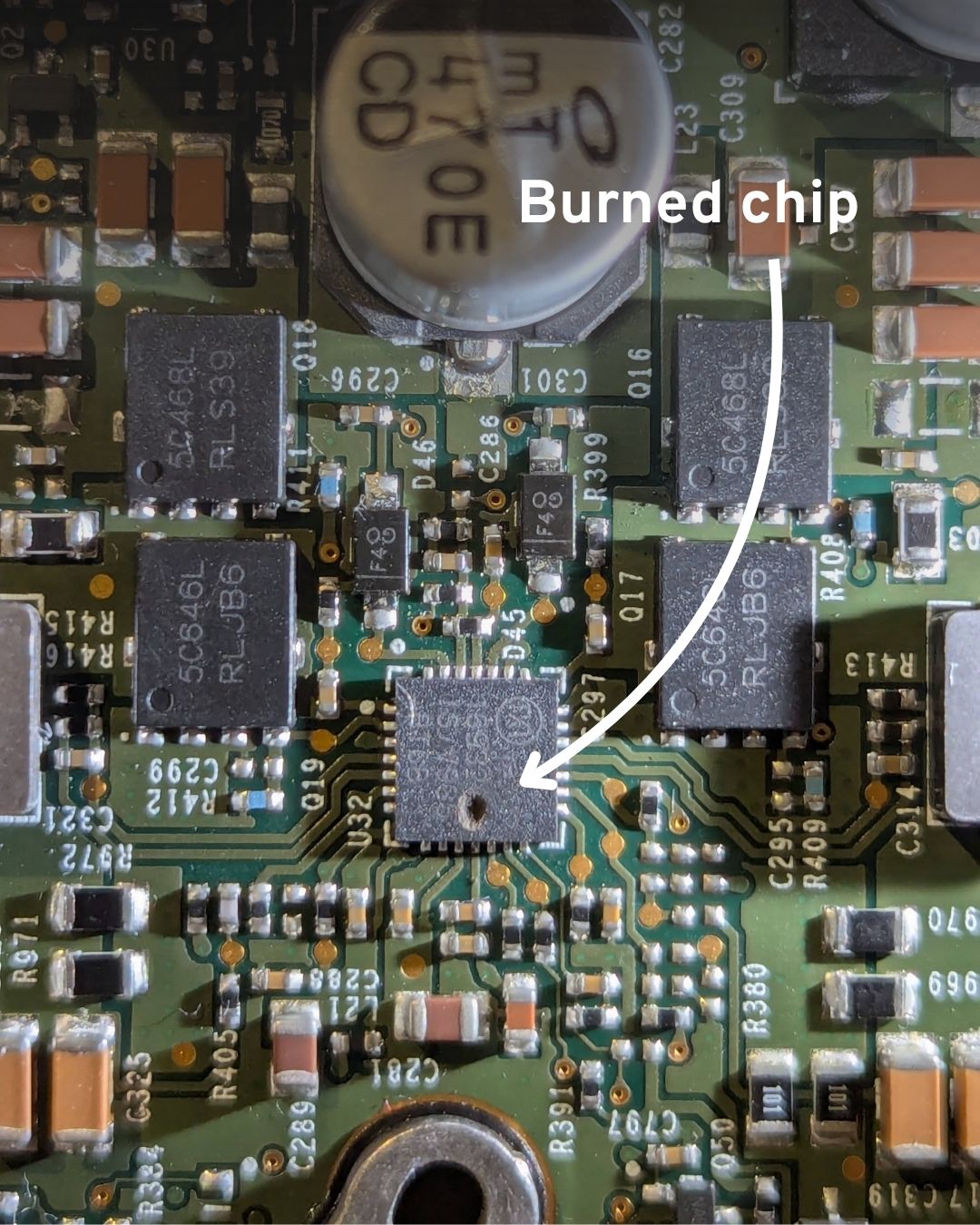
It was extremely hard to find the name/model of the chip that got burned, especially since part of the text printed on it had become unreadable due to the damage. To be able to continue with the project, I had to order a whole other car computer.
In the meantime, my friend Yasser (@n3r0li) somehow pulled off the impossible and identified it as the “MAX16932CATIS/V+T” step-down controller, responsible for converting power down to lower voltages. We ordered the chip and took the board to a local PCB repair shop, where they successfully replaced it and fixed the MCU. Now I had two computers to work with.
So I really did need that Rosenberger cable, there was no getting around it.
After having no luck finding it online and even visiting a Tesla service center in London (an odd encounter, to say the least), I had to accept what I had been trying to avoid: buying an entire Dashboard Wiring Harness.
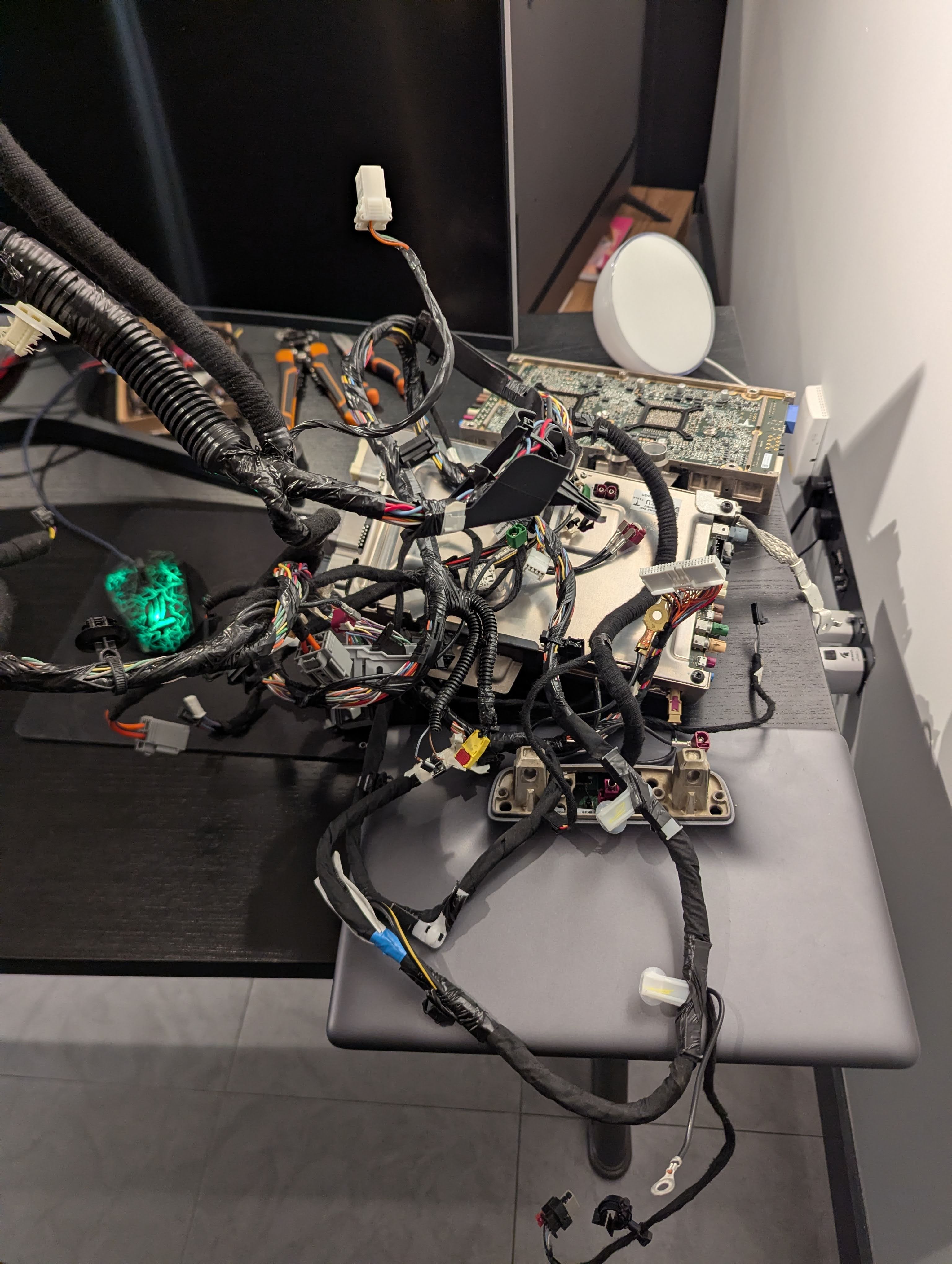
Back in the Tesla Electrical Reference, in addition to the connectors, one can find every part number. Looking at the cable which connects the MCU to the screen, the number 1067960-XX-E shows. Searching for it on Ebay brings up this monstrosity:
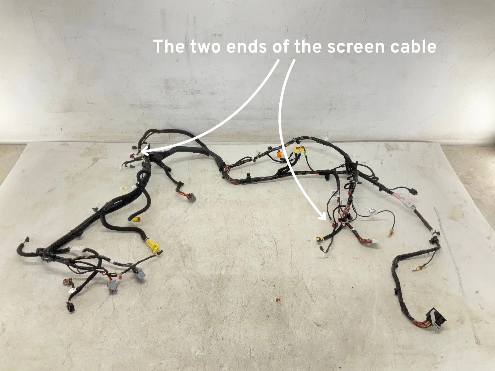
Turns out that actual cars don’t have individual cables. Instead they have these big “looms”, which bundle many cables from a nearby area into a single harness. This is the reason why I could not find the individual cable earlier. They simply don’t manufacture it. Unfortunately I had no other choice but to buy this entire loom for 80 USD.
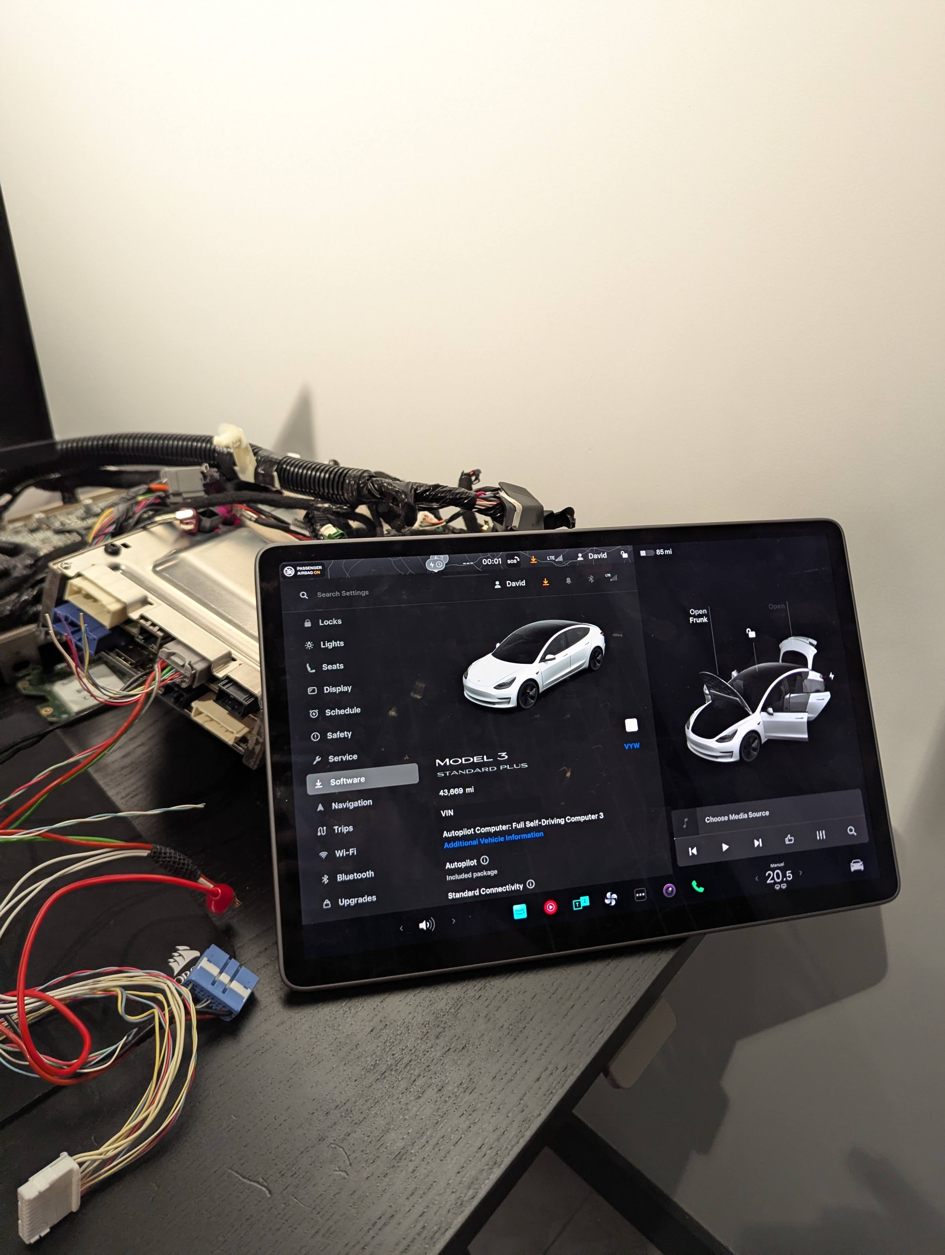
Despite how bulky it was, the loom worked perfectly. The car booted, the touch screen started up, and I had a working car computer on my desk, running the car’s operating system!
Having the system running, I can now start playing with the user interface, interacting with the exposed network interfaces, exploring the CAN buses, and perhaps even attempting to extract the firmware.